TUTORIAL: LFO
2015.07.27In this series of tutorials, we will explore the parameters and history of the legendary ARP Odyssey in its current, reissued form. Here, we will focus on the connectors. Here, we will discuss the LFO. Text: Ryota Hayashida (Iroha Studio)
LFO
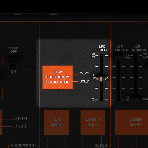
The LFO (low frequency oscillator) is an oscillator that continues producing a cyclically-constant control signal regardless of what you play on the keyboard. Although it cannot be used as an audio signal, it does have a variety of uses. The LFO section has only a FREQ parameter that changes the speed, but actually does let you obtain two types of waveform: sine wave and pulse wave.
If the LFO is used as a modulation source for VCO, you’ll get a vibrato effect. If it’s used to open and close the filter, you’ll get a wah effect. By taking advantage of the fact that the waveform is cyclically modulating at consistent timing intervals, you can use it as a detection timing source for the S/H discussed below, or as a signal to successively trigger the envelope.
Although this is a function that was not found on the original ARP Odyssey, an LED blinking in synchronization with the LFO rate can be seen from the opening in which the LFO slider moves. It is surprisingly useful to have a visual indication of the LFO speed.
S/H (SAMPLE & HOLD)
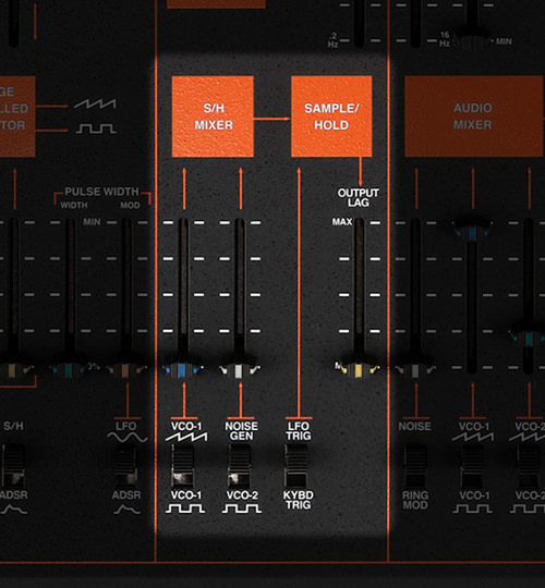
Sample and hold is a module that generates a unique control signal. The signals combined by the S/H MIXER result in a rapidly varying voltage that can affect other parts of the signal path.The VCO and the noise generator can be used as sources. These audio signals are not perceived as stable sound, but are constantly changing in complex ways. Next, at the timing determined by the LFO or keyboard trigger, the source voltage is instantaneously “sampled” or “detected.” The voltage that is detected at that time is whatever source voltage happens to be present, so the detected value is fairly random. For example, if the source signal is a random one like noise, a different random voltage is obtained each time the signal is sampled. In other words, there is always an element of randomness in the value detected by S/H.
The detected voltage is then held until the next detection, and this is the basic operation of S/H. The random chirping sounds associated with computers of the past can easily be produced by using pink noise as the source, making the LFO mark the timing interval, and then using the result as an FM modulation source for the VCO. This is also a good way to hear basic S/H in operation. Raising the OUTPUT LAG will apply a portamento-like effect to the changes that occur in the detected voltages.
 VCF / VCA